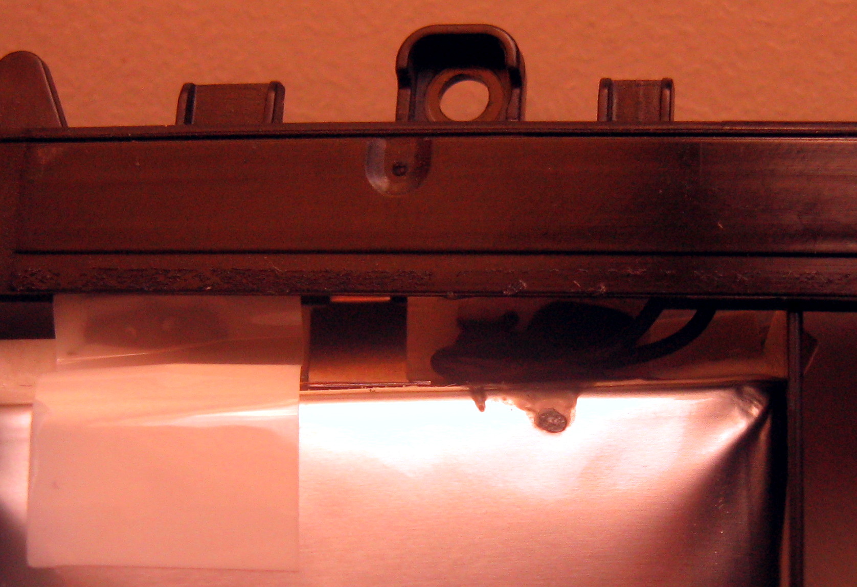
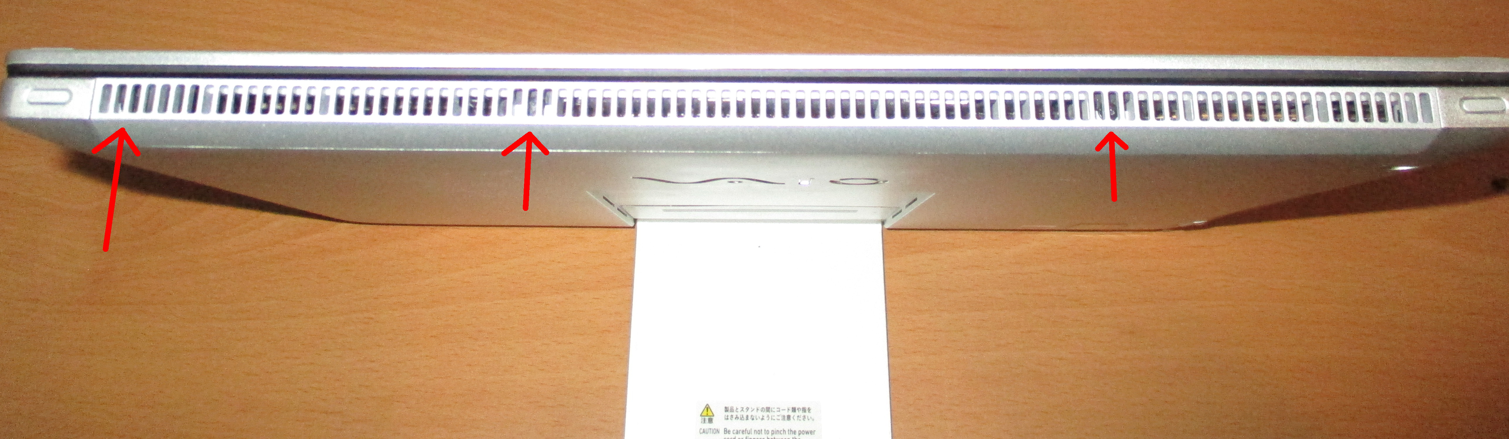
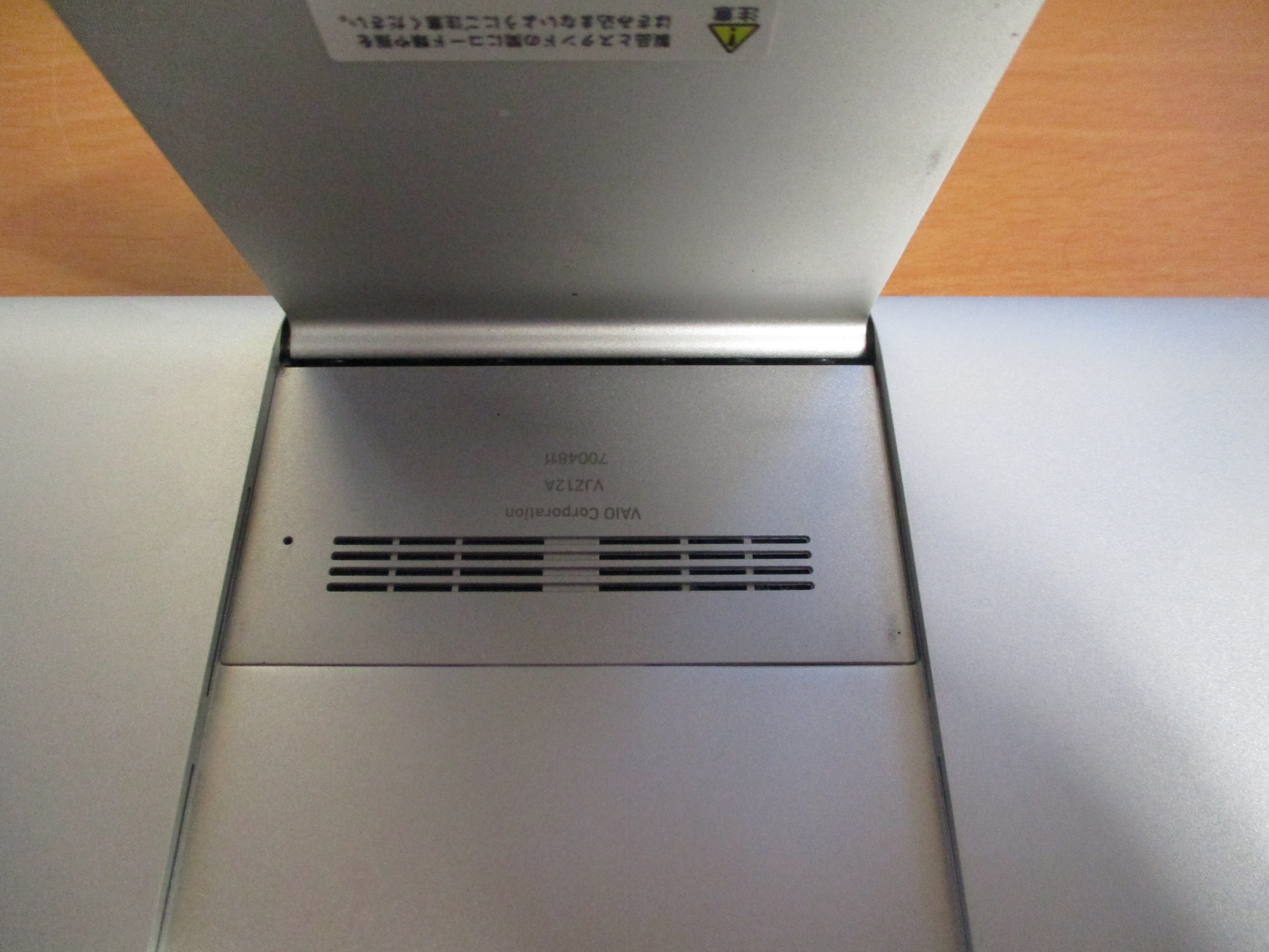
Loosen the three screws underneath the top grille, as located below.
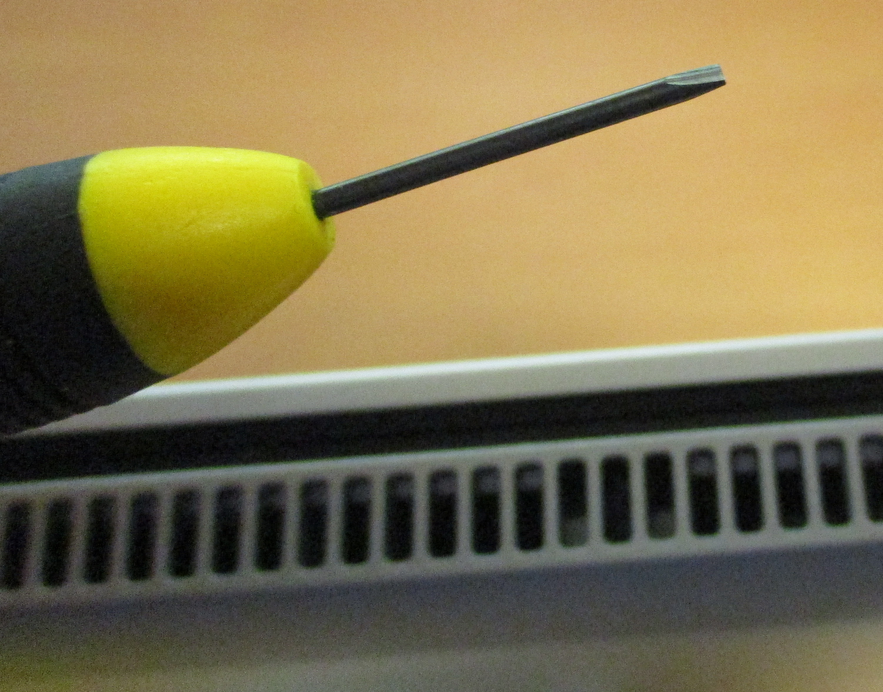
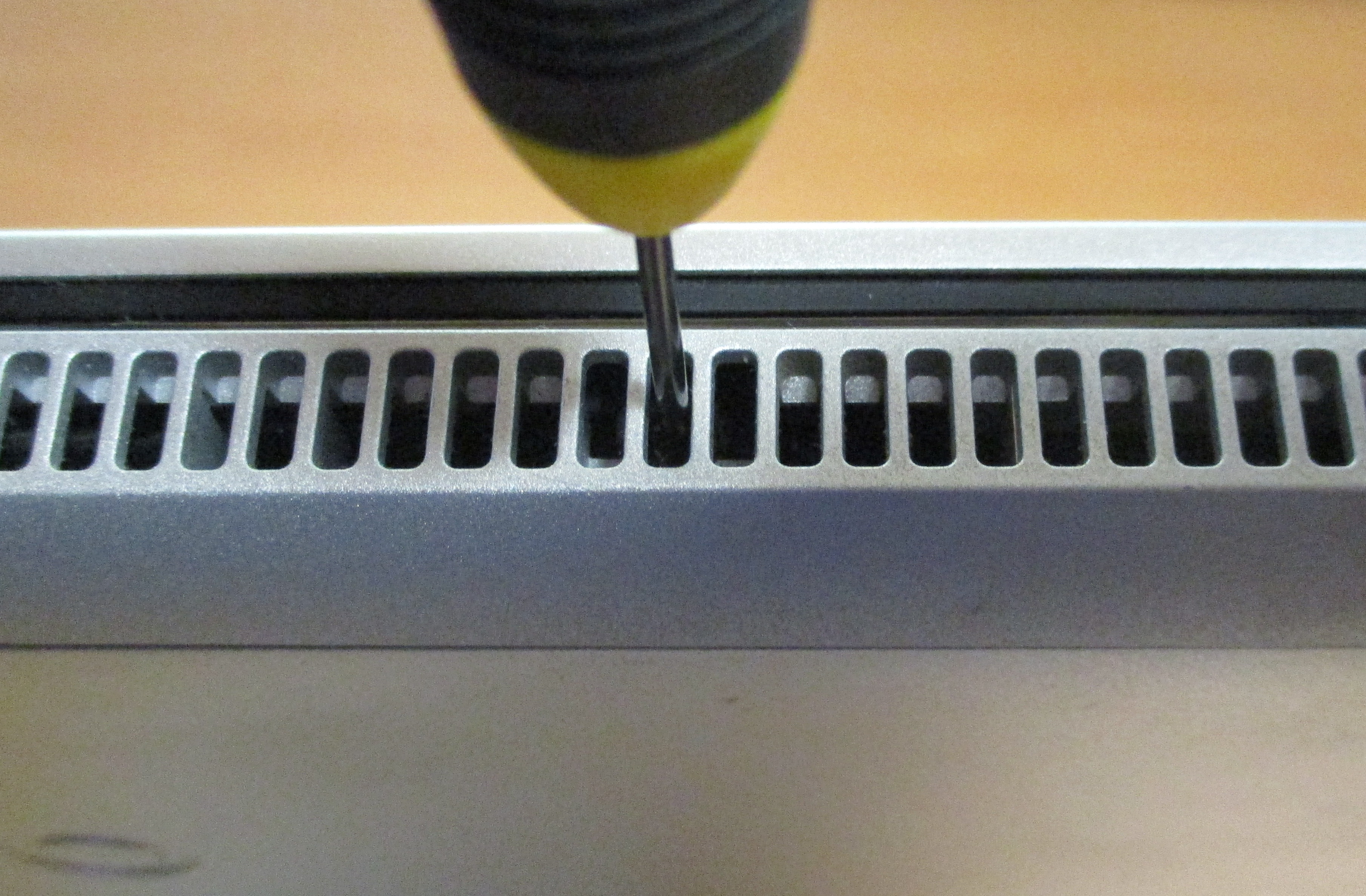
Use a 1.4mm flathead screwdriver, as shown below, to reach between the bars of the grille to loosen these screws. The flathead screwdriver works despite the screws being phillips head. Loosen the screws approximately 3 turns, but do not remove them. If you do unscrew them all the way they will drop down inside the computer.
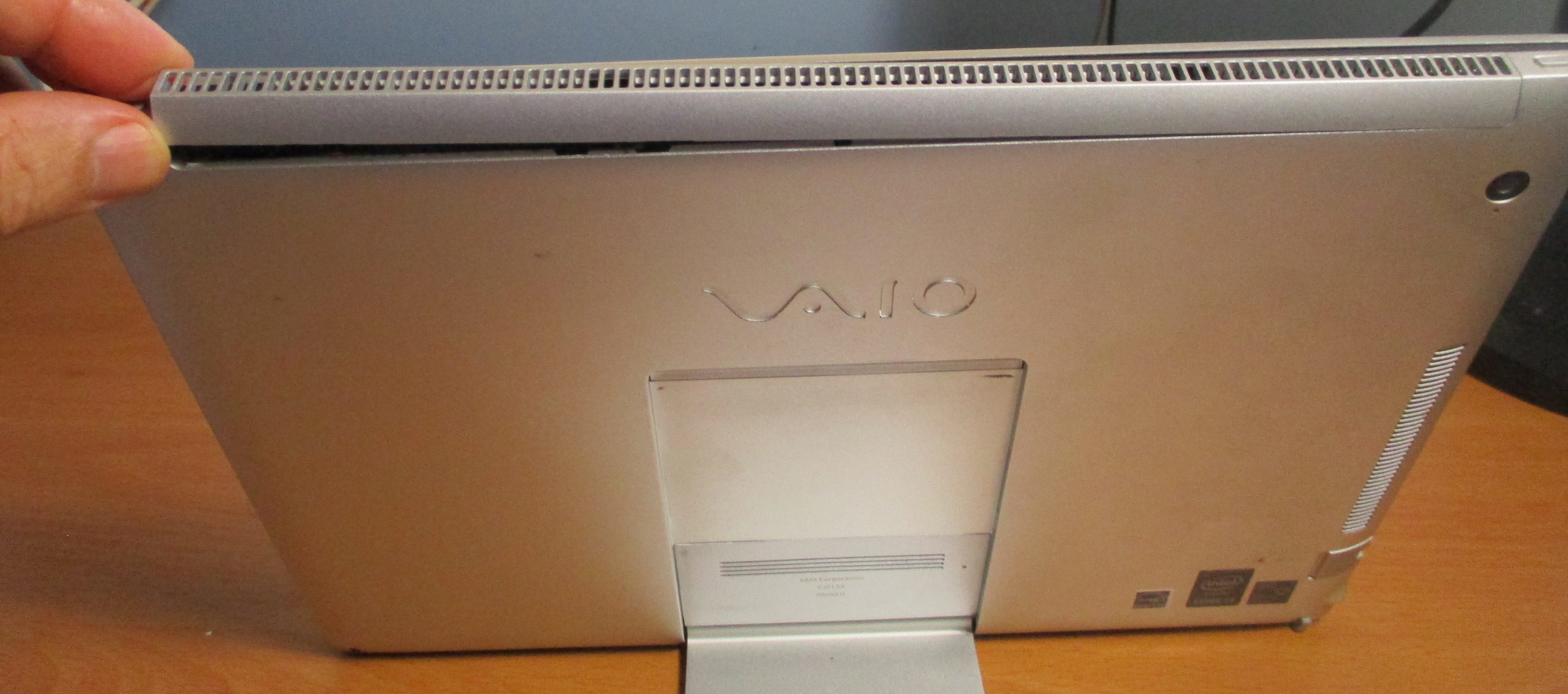
Gently pop the grille off, starting from the left hand side as you look at the computer from the back. The screw holes are slotted, allowing the grille to pop off backwards whilst the screws are still in place. The right hand side of the grille has a lug on it, which fits into the body and is the reason why the other end has to be removed first. Assembly is the reverse of disassembly, whereby you locate the lug first, then ease the rest of the grill into position, making sure the slotted holes go under the heads of the screws and the grill progressively clicks into place.


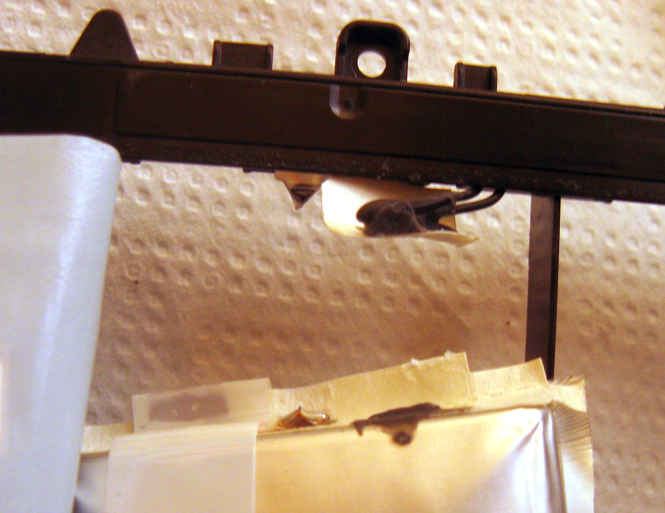
Slide microphone out, so it is no longer attached to the screen
Unloop wifi antenna cables from around the pegs under the grille

When assembling the computer, make sure the WiFi antenna cables run between the battery and fan, and are not sitting on top of either. Otherwise the screen will press down on the cables and the computer won't close properly. Also make sure the cables don't get in the way when you are trying to line the screw holes up under the grille, thus preventing the screw holes from lining up. You may need to use a small screwdriver to push the cables down a little.
Remove the access hatch on the rear of the computer. To do this, place the keyboard over the screen to protect the screen, then place the computer screen down. Hook your fingernails into the slots of the grille on the access hatch and gently slide the hatch towards the stand. Once enough force is applied, firmly but gently, it will slide a few millimetres with a click. You can then use your fingernails in the slots of the grill to lift the access hatch out, or turn the computer over to let it drop out.

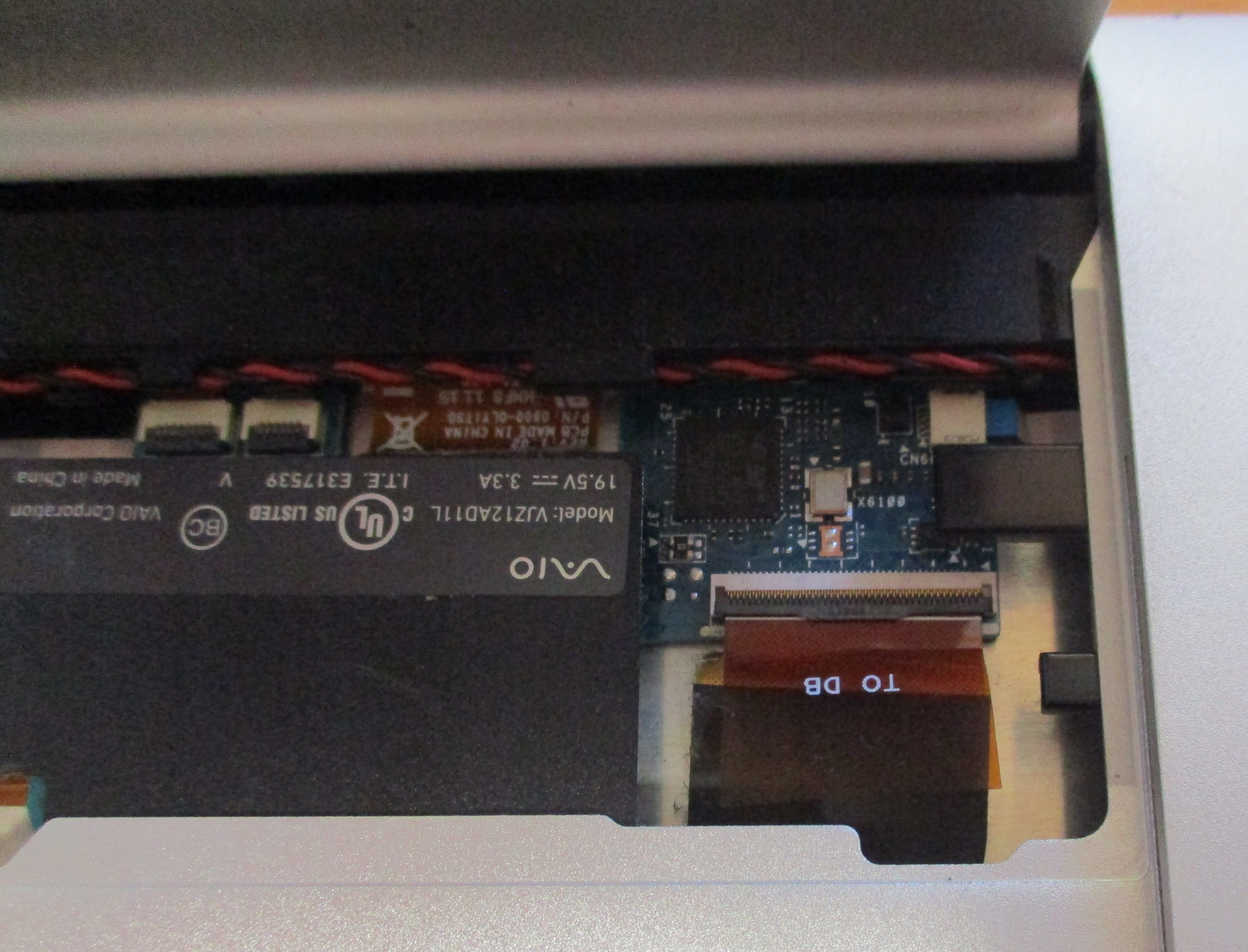
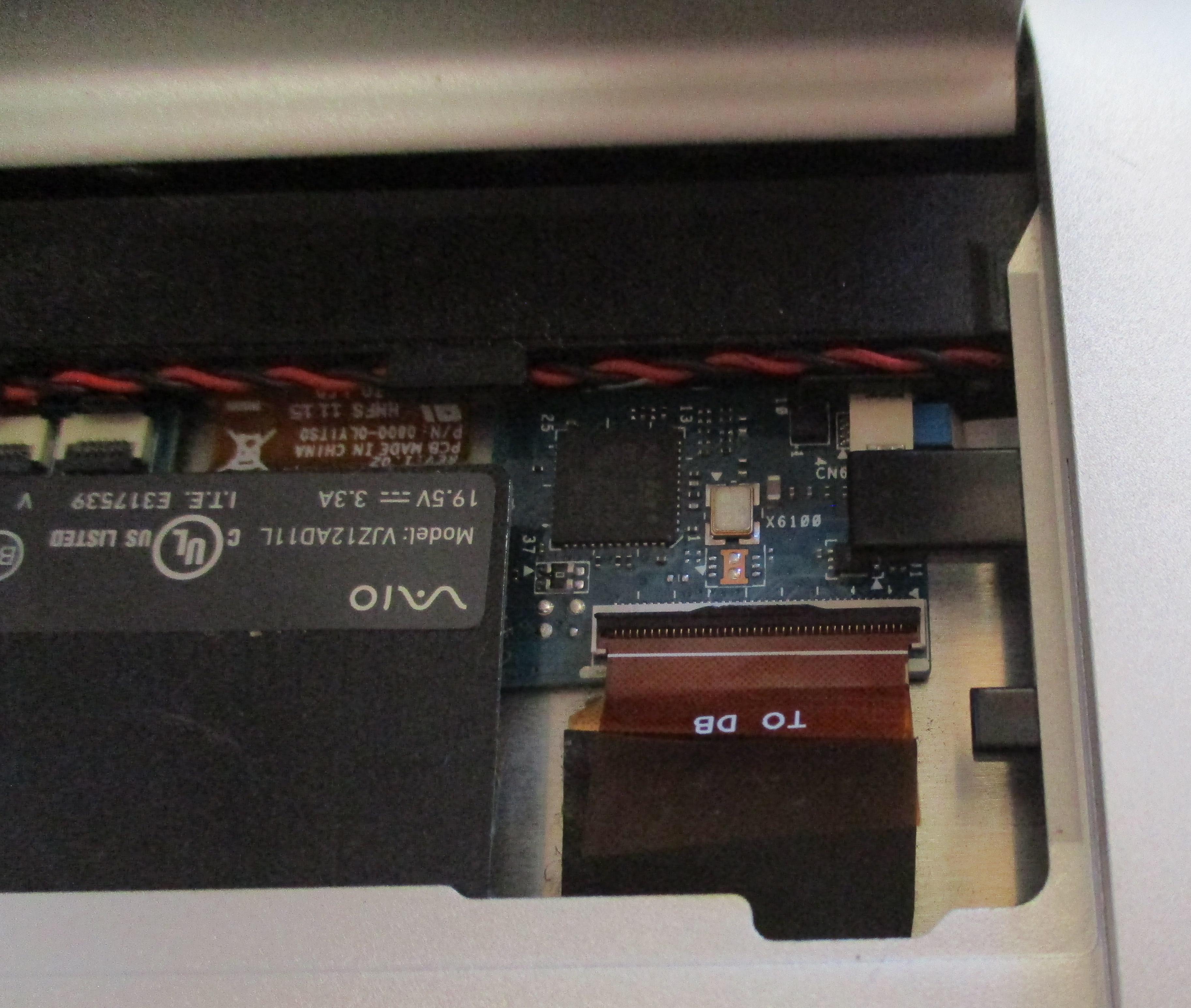
Once the access hatch is removed, you will see the cable that connects the screen to the motherboard. Remove this cable as follows. Use a fingernail to lever the retaining latch up on the connector. You can then gently lift the cable up and out, using the plastic tag which is on the end of the cable as a handle.
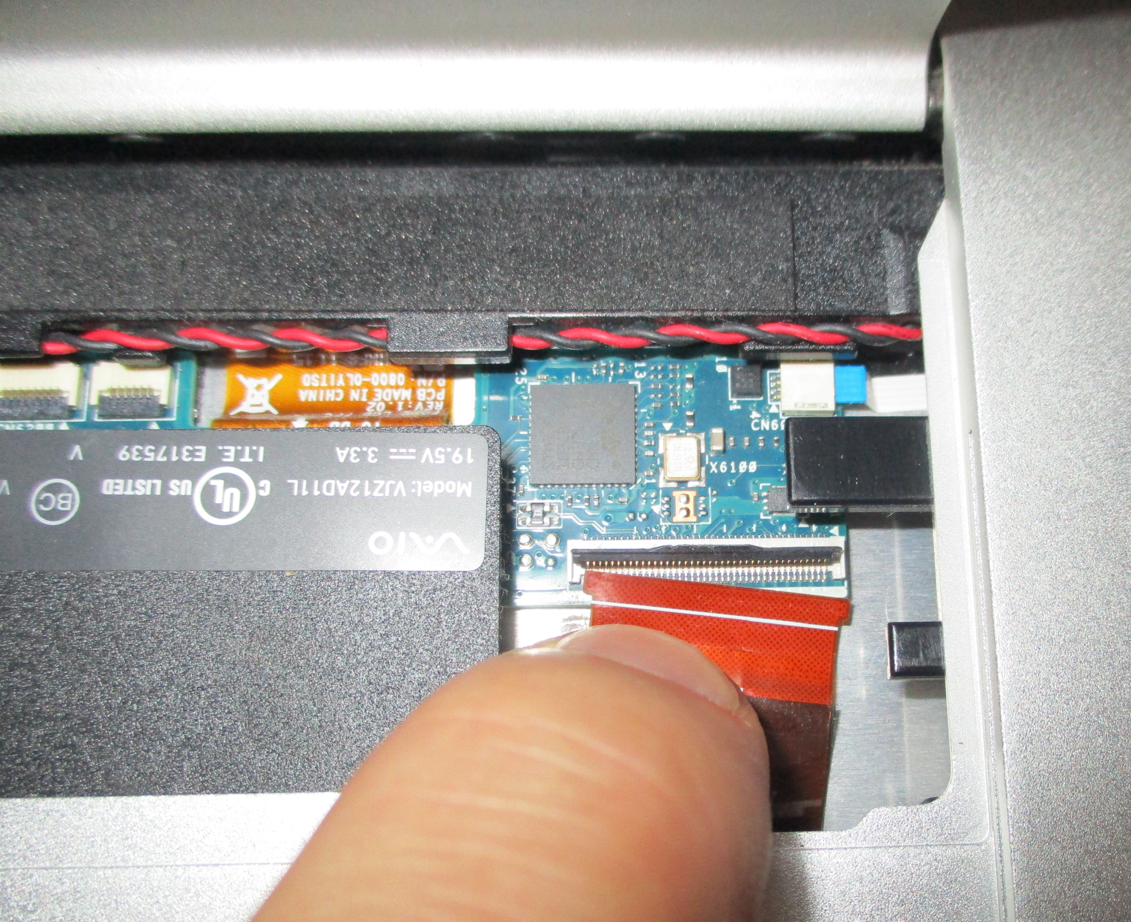
Assembly is the reverse of disassembly. First seat the cable into the connector, using the plastic tag to manupilate the cable into position. The end of the cable slides into the connector first and fits under the latch. The tabs either side of the contacts fit into the recepticle, so the cable is lying flat. The latch can then be pushed all the way down, so it sits flat and clamps the cable in position. If the latch doesn't go down easily then the cable might not be in position properly.
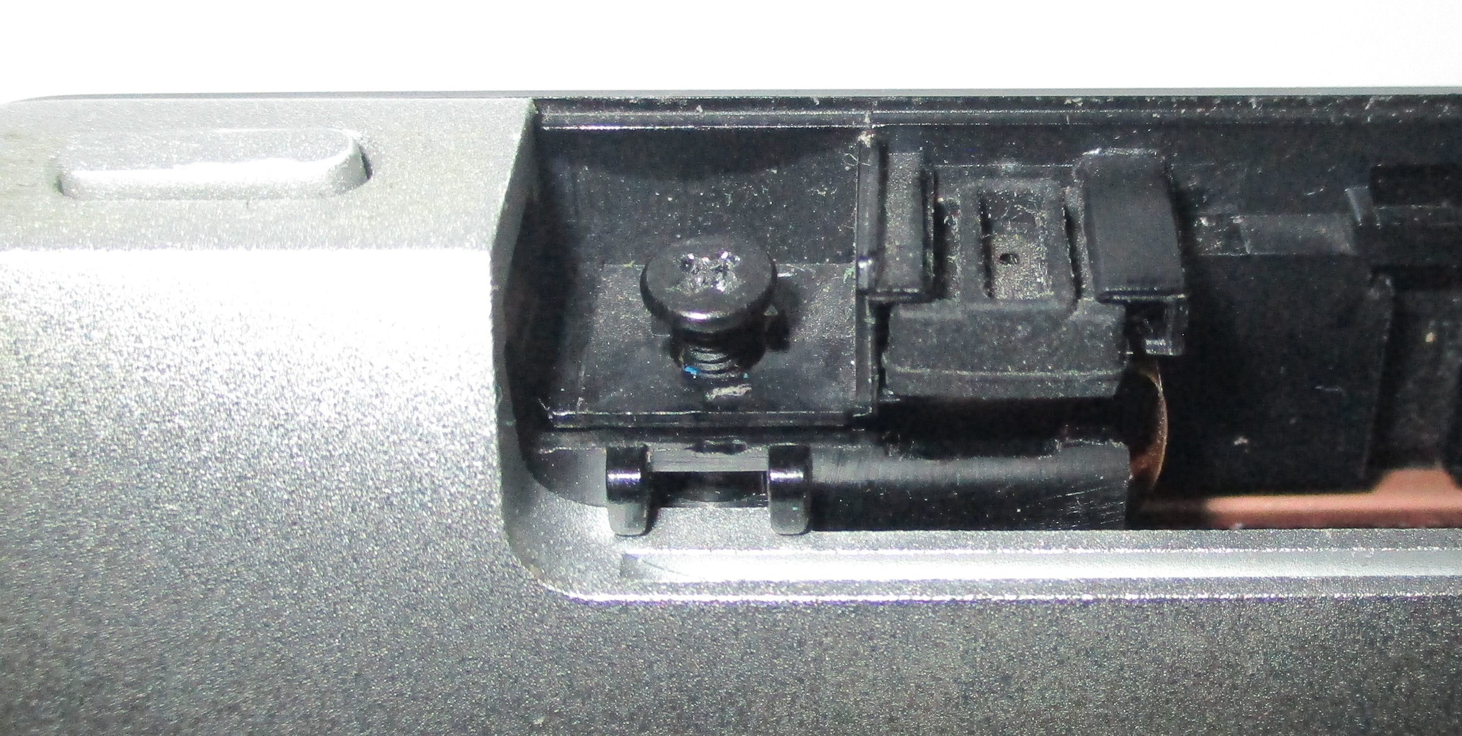
You can now remove the screen and bezel from the backshell of the computer. To do this, you will need to slide the screen about 2 millimetres upwards. The screen is held on by a set of latches, which are shown below.
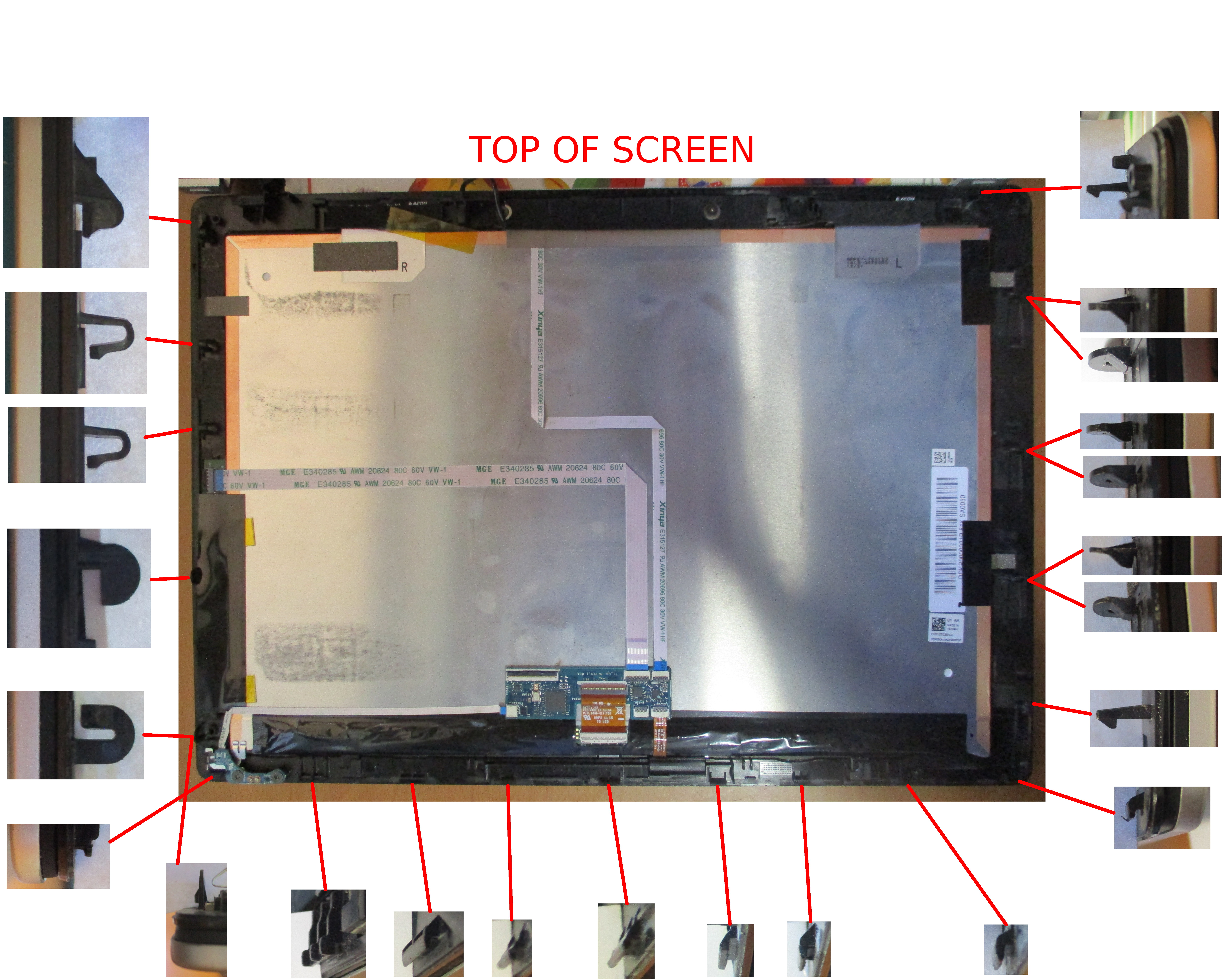
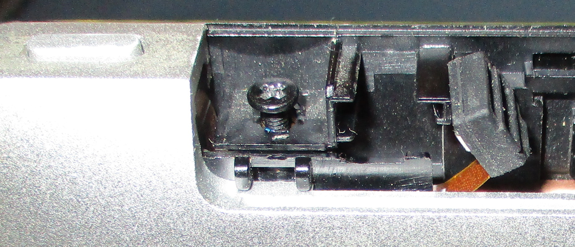
The latches are designed so they will release when the screen is slid up approximately 2mm. There are also a couple of pegs at the top corners of the screen, which will prevent the screen from starting to slide. The locations of these pegs are shown below.
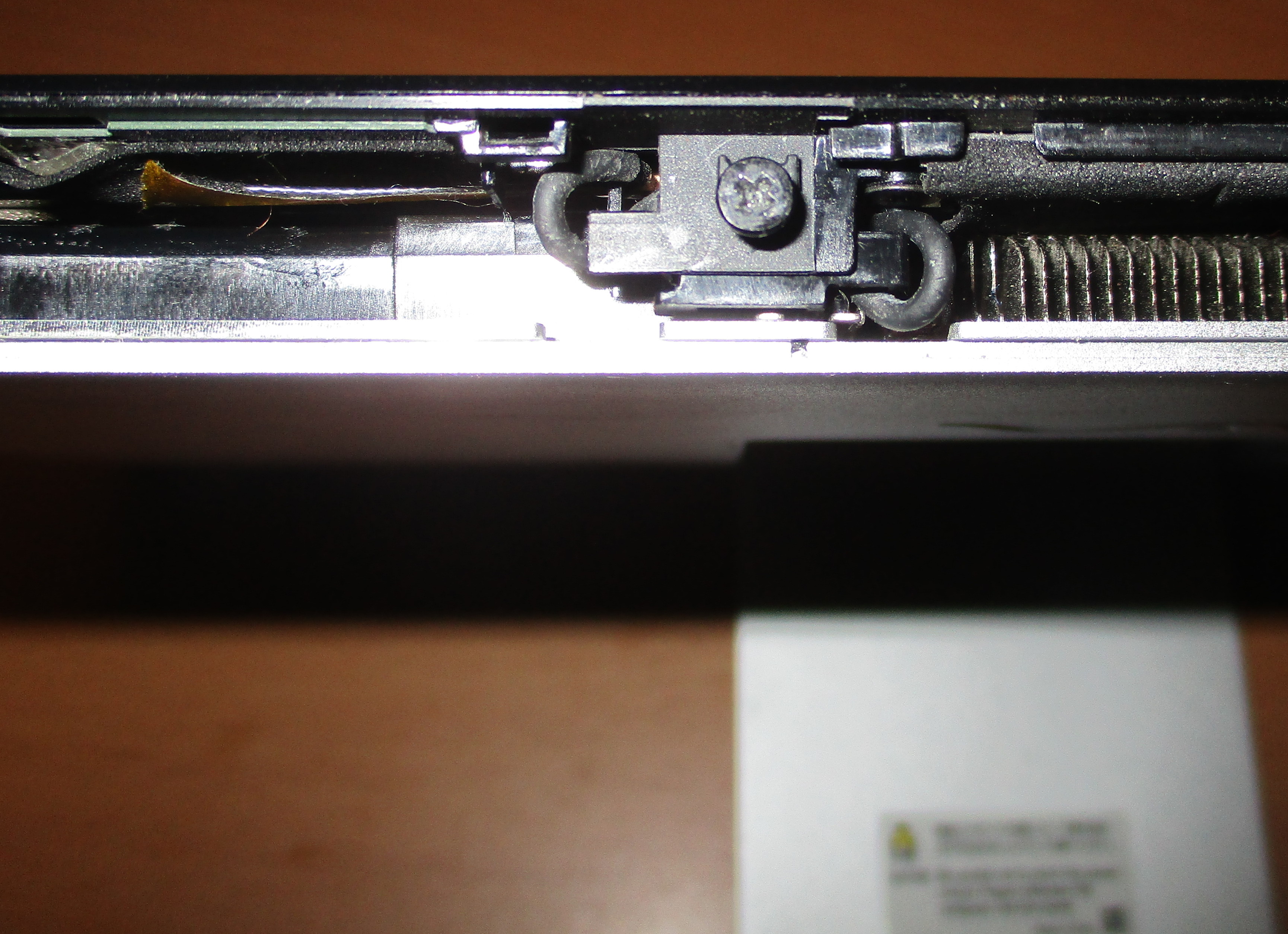
To start sliding the screen, you will need to lever the top corners of the screen out far enough that the above pegs clear the edges of the case. Once sliding, you will find that the latch ot the top right of the screen will be the hardest to release when sliding the screen out. During disassembly, this latch will also be the hardest to get in. The image below shows how far you have to slide the scren up to release it.

If the batteries in your computer are swollen and bearing against the back of the screen then it may be harder to slide the screen up.
Once the screen is released, you can pivot it away from the backshell. Be sure to pivot the bottom up and keep the top edge of the screen close in, as if you are opening a book, where the top edge of the computer is the spine. This will prevent the WiFi antenna cables, which still run from the motherboard to the screen, from being damaged.
Once the computer is open, you can remove the battery by taking out seven screws which hold its plastic frame to the case. There are also two screws in the battery connector. Once these screws are removed, the connector lifts straight off. You will also need to remove a bit of yellow tape, which is holding the WiFi antenna cables in position, and a blob of glue that attaches the microphone cable to the top edge of the battery. Take note of the routing of the WiFi antena cables before disturbing anything, so you can reproduce the routing when you reassemble the computer.
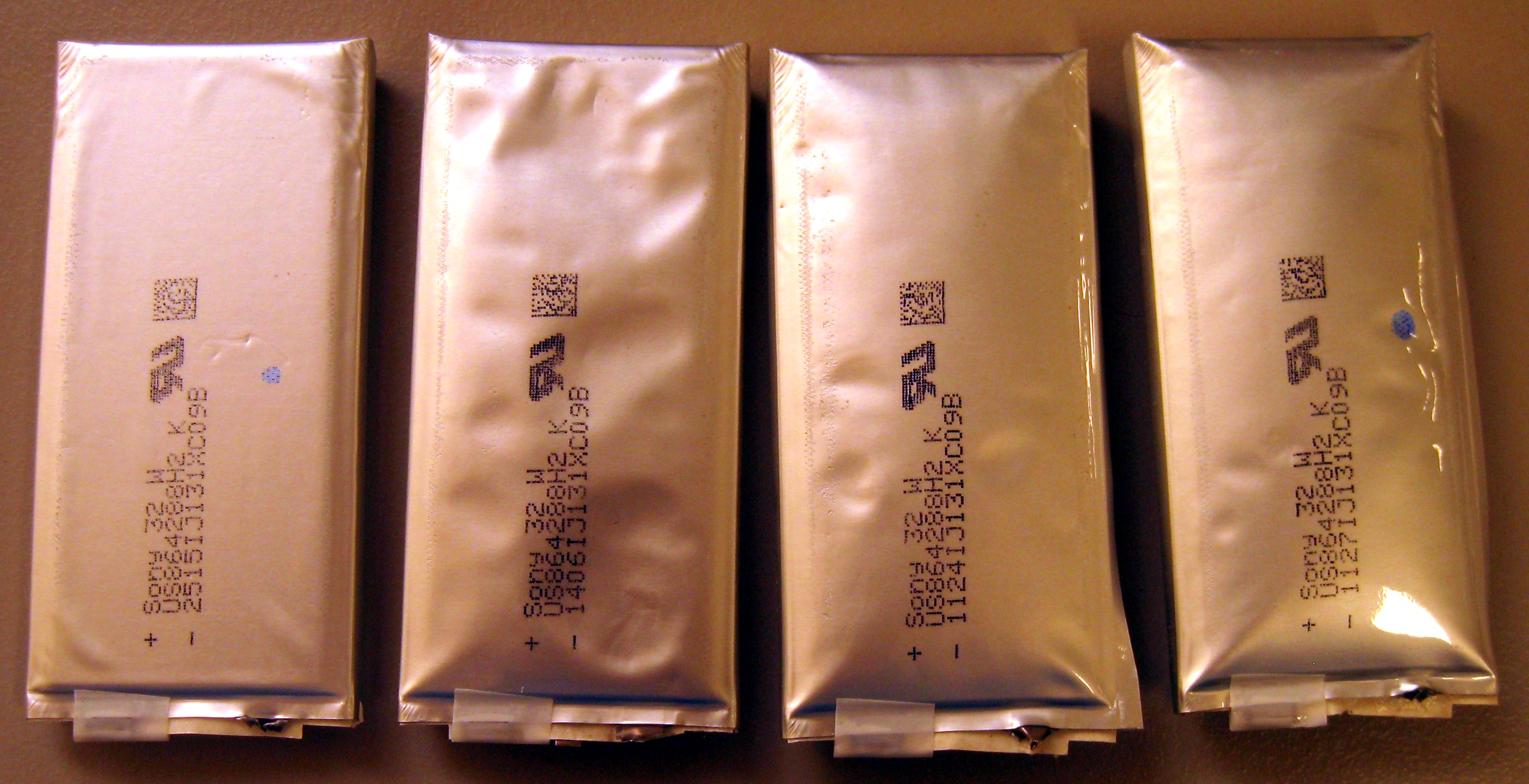
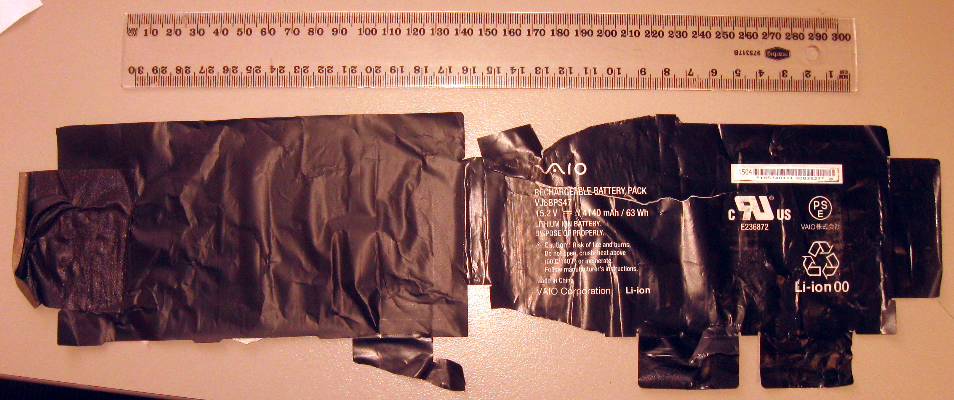
You can dissasemble the battery pack by peeling the outer plastic cover off, leaving the four sealed (and potentially swollen) cells exposed in the plastic frame. I removed the cells by carefully snipping off their terminals, being very careful not to short the terminals whilst snipping, or to leave any loose burrs of metal. The cells then lift out, with the exception of one cell which has a temperature sensor glued to it. This sensor may be carefully peeled off the cell, as shown below. I then reinstalled the empty battery frame, with no cells, and reattached the battery cable. The computer will happily operate without cells in the battery.